| “ | Please note that Circuits are not yet for the faint of heart! This is an early version, so there'll be bugs and incompleteness. We absolutely apologize for any frustration this causes!
|
” |
— Rec Room Inc., Update Page
|
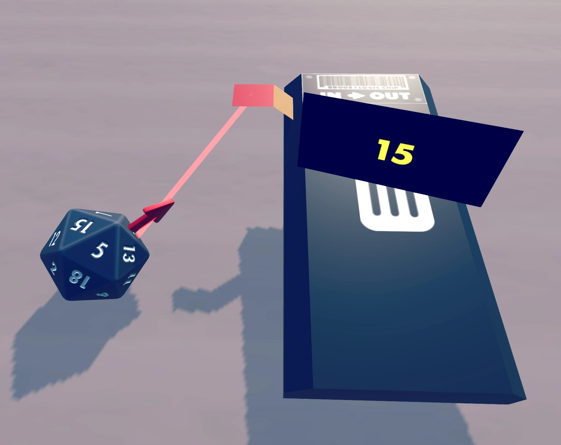
Example of a simple circuit: a 20-sided die wired to an Output chip to display the rolled number.

Introduction to Circuits
YouTube tutorial by Rec Room Inc.
About
Circuits are editable networks of Chips, Gizmos, Other Gadgets, Dynamic Props and Circuit Boards that can be used in Custom Rooms to execute more or less complex programs. These programs can control animated and interactive elements of a room, for example, animated or interactive spot lights, sound effects, holotar projections, or complete games.
By default, only creators and co-owners of a Custom Rooms have the Permissions to view circuits and edit them with the Maker Pen and the Palette. Circuits consist of Chips, Gizmos, Other Gadgets, Dynamic Props, and Circuit Boards, which can be configured with the Configure mode of the Maker Pen. Their pins can be connected and disconnected with the Wire mode of the Maker Pen.
If you have questions about specific circuits or the system in general, check out Arcade questions tagged with [rec-room] and don't hesitate to ask your questions in the #gadgets channel of the Rec Room discord. There are also classes about circuits in the Creator Programs organized by Rec Room Inc.
Examples of Circuits

Rec Room How To Maker Pen Crash Course
YouTube video by AfewGoodTacos, which is part of Rec Room Inc.'s YouTube playlist "Community Tutorials (Creative Tools)"
Many examples of useful circuits are documented in Circuit Diagrams.
Several players have created YouTube videos about circuits; see Rec Room Inc.'s YouTube playlist "Community Tutorials (Creative Tools)", their support page with custom rooms tutorials and the #tutorials channel of the Rec Room discord.
You can see many circuits in Rec Room by going to Custom Rooms like ^CircuitAcademy0, ^CircuitsForDummies, ^circuitdemo, ^circuitrecipes, ^TeamandStatscircuits, ^GameModeCircuits, ^GizmosAndTags, ^DoorGizmos, ^Gizmos2WavesItemspawns, ^TutoNPC, etc. To find these rooms, open your Watch Menu, click on the Play button and then the Search tab. Click on "Enter name here," type in the name, and then click the "Search" button.
Circuit Nodes
Apart from wires, circuits consist of various circuit nodes, i.e. Chips, Gizmos, Other Gadgets, Dynamic Props, and Circuit Boards, which can be configured with the Configure mode of the Maker Pen. The pins of circuit nodes can be connected (and disconnected) with the Wire mode of the Maker Pen to send signals to or receive signals from other circuit nodes. (The system is based on the dataflow programming paradigm.) You can get information about most pins (description and current value) by pointing with the ray of the Maker Pen (for example in Wire mode) at a pin for about 2 seconds.
Circuit nodes process their signals about 10 times per second. The system evaluates circuit nodes in a particular order, i.e., a circuit node that produces a signal for another circuit node is usually evaluated before the other circuit node is evaluated (except in cases of cycles where the evaluation order depends on the order in which the circuit nodes were connected). Thus, if there are no cycles, a signal can travel from a circuit node at one end of a circuit to a circuit node at another end of the circuit within just 1/10 of a second. This is referred to as a "circuit tick".
Circuit nodes include gadgets, props, and circuit boards as described next.
Gadgets

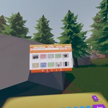
Gadgets tab of Palette. 1st page of Other Gadgets.
Most circuit nodes are listed in the "Gadgets" tab of the Palette.
Chips
See Chips.
Gizmos
See Gizmos.
Other Gadgets
See Other Gadgets.
Dynamic Props

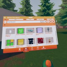
Props tab of Palette. 1st page of Dynamic Props.
Dynamic Props are circuit nodes that are listed in the "Props" tab of the Palette with the filter "Dynamic". (Very few props in other categories are also described on the page about Dynamic Props.)
Circuit Board
Circuit Boards can combine multiple Chips into one circuit node.
Data Types
Circuit nodes can only send integer values to other circuit nodes, but internally they might use different types. Therefore internal values might have to be converted to and from integers.
Integer
The native circuit values are 32-bit signed integers: They range from −2,147,483,648 to 2,147,483,647 and cannot produce fractions or real numbers.
Boolean
Many inputs and outputs use an integer value to represent only two Boolean values, i.e., false (a value equal to 0) and true (any value unequal to 0). For inputs, that means that 0 is interpreted as false, any other value as true. For outputs, that means that 0 is emitted for false and 1 for true.
Float
Gizmos, for example, convert their inputs to floats. The value range of floats is larger than that of integers, so you can pass any integer number and it can be used. However the precision of a float depends on how close the number is to 0; the precision falls below 1 outside the range of -16,777,217 to 16,777,216. In other words, you can input and use 16,777,216 just fine, but 16,777,217 will have the exact same result as it is rounded to 16,777,216.
ID
Some chips use integer IDs as inputs or outputs. Those are numbers that uniquely identify entities:
Player ID
Every player gets an ID when the player joins the Room, and that ID is valid until the player leaves.
Your player ID is equal to your index of joined players in that room, meaning the first player to join gets ID 1, the second gets ID 2, and so on. If a player leaves and rejoins, they are given a completely new Player ID because rejoining is not different from joining. Player IDs only repeat after a Room becomes completely empty (because the room instance stops existing for that time). If a Room stays populated for a long time, with many players leaving and joining (or rejoining), there is no true limit to how large assigned Player ID values can become.
For Circuits, a player ID of -1 will apply to all players; this is useful, for example, if you need to set everyone's health.
Team ID
Every team has a different ID, ranging from 1 to 16.
Team Index
When a player joins a team, they are given the lowest currently unused Team Index for the joined team, starting at 1. Team Indices may be re-used (this is notably different from Player IDs, which always increase in value). When a player leaves a team, the player's Team Index remains unused until a new player joins and receives it.
This means that the range of valid Team Indices can't directly be determined from the number of players on that team. Instead, use the Player Event Chip and the Team Mapping Chip (player to team) to track the index of a player entering or leaving the game.
Object ID
Every object has a unique Object ID number. Trigger Volumes can get an object's ID which can be sent to the Object Mapper chip to get the ID of the player currently holding the object. Object IDs stay the same until a room is saved or restored, then everything gets new IDs. You can use a Randomiser Chip to store an Object ID, by connecting the Red pin on an Object Trigger to all three pins on the Randomiser.
Color ID

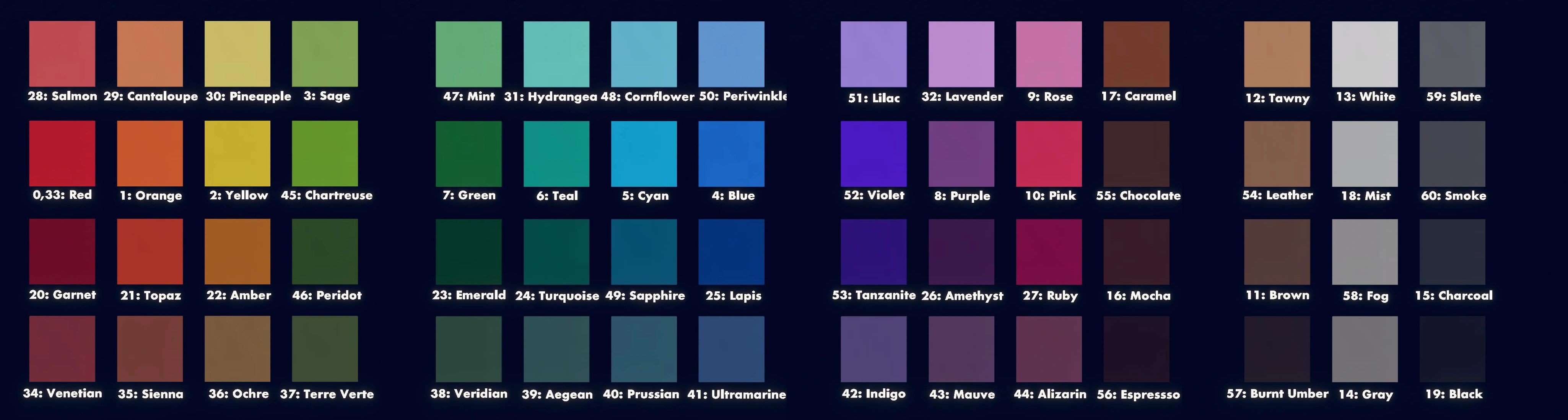
Colors for Emitters, Point Lights, Spotlights, Texts, Beacons, and Stage Lights are specified by a Color ID that corresponds to one of the 33 colors on the Palette: red (0), orange (1), yellow (2), sage (3), blue (4), cornflower (5), teal (6), green (7), purple (8), rose (9), pink (10), brown (11), tan (12), white (13), gray (14), charcoal (15), mocha (16), caramel (17), light gray (18), black (19), garnet (20), topaz (21), amber (22), emerald (23), turquoise (24), lapis (25), amethyst (26), pink gemstone (27), salmon (28), cantaloupe (29), pineapple (30), cyan (31), and lavender (32).
Other Color IDs should probably not be used since the resulting colors are not consistent and they are changed relatively frequently with new updates. At the time of writing, negative Color IDs are mapped to 0 (red) for Texts, Point Lights, Spotlights, and Stage Lights. For Beacons, negative Color IDs are mapped to 13 (white). For Emitters, negative Color IDs are mapped to a default color depending on the effect. The Color ID 33 represents varies colors (red, white, or no change). Color IDs greater than 33 are mapped to values between 0 and 33 by a modulo 34 operation, i.e., 34 is mapped to 0 (red), 35 is mapped to 1 (orange), 36 is mapped to 2 (yellow), etc.
Material ID
Materials for Texts are specified by a Material ID. [more information needed]
Pitfalls
The current version of circuits has some known pitfalls that can be hard to understand if you are not aware of them.
Invisible Circuits
The capability of using a Maker Pen and viewing gadgets is controlled by Permissions in a room. Thus, if you don't have the Permissions to edit circuits for a particular room, you might have to ask the creator of the room to give you such permissions.
Connecting Frozen Objects
Wiring frozen objects is currently not possible. You have to unfreeze both objects with the Freeze mode of the Maker Pen before connecting them. It should be noted that frozen objects can still be connected to Gizmos.
Connecting Shapes to Gizmos
You cannot connect Maker Pen shapes to Gizmos, but you can connect Maker Pen objects to Gizmos. To turn a shape into an object, press the "Done Editing" button of the Maker Pen.
Value Range
Circuits currently support only 32-bit signed integers as signals. They range from −2,147,483,648 to 2,147,483,647 and cannot produce fractions or real numbers.
Ring Evaluation Order
A Chip that produces a signal for another chip is usually evaluated before the other chip. However, this does not work if signals travel in cycles (rings) formed by connections between chips. To evaluate a chip in a cycle the game would need to calculate the result of an infinite looping evaluation. Instead already evaluated chips are not evaluated again. We call the order in which the game chooses to evaluate a ring the Ring Evaluation Order.
This can lead to unexpected results if the game chooses to evaluate the chips in a different order than you intended. For example if you have two nodes in a loop, and the chip that you think is second is actually evaluated before the one you think is first, it appears like the second chip receives or outputs it's information with a delay of one tick.
The game resolves rings like this: If a connection closes a loop the time when it is drawn, the connection will become a special connection that we will call Loop Closing Connection (LCC).
- LCCs are only created if the loop would otherwise consist of regular connections.
- If you open the loop by removing a different connection, the LCC persists.
- An LCC will not be considered finding the order in which the chips are evaluated at all, allowing the game to resolve rings in the circuit graph.
- An LCC without a loop will either delay the evaluation of the chip it is connected to, or not. Sometimes it will even stop working completely. The behavior is consistent across saves and clients, but changes for clones. It is unclear how the game decides which behavior to chose, but it seems to be related to the order in which the loop is connected to other chips.
- If there is an LCC between chips A and B, but there also is a regular connection between A and B, both connections will behave as if they were regular.
- TODO: Find out how the second order is defined. In case there are multiple LCCs in a new loop, how does the game decide which one to delay again?
One way to intentionally create LCCs is using the often unused reset pins to create loops that would otherwise not exist. It does not matter if actually is any input to the reset pin.
The State Machine is a special case: Every state of the state machine is also in the same evaluation node as the state machine itself. A state-event pin connected to an seemingly unrelated transition in the same state machine will thus form a ring.
Authority Player
Circuits (among other things) are evaluated not on any RR server, but on the client of the player who enters a room first; that player is called authority player. When the authority player leaves, another player becomes the new authority player.
The client of the authority player publishes circuit results to other players in the room. This causes extreme lag (in the order of full seconds), if other players than the authority player cause circuit evaluations (by triggering zones or buttons, shooting people, etc.). In addition to that, the implementation of the authority player functionality has always been buggy and still causes synchronization problems between clients. As a result, the game state observed by the authority player and the state observed by anyone else often do not match, the world might even change when a new authority player is chosen (sandbox radios for example start playing again).
Global Chip Update Tick

Changes:
- Rec Royale Alpha Update: The random number generator chip is not affected anymore. The effect can still be observed with the new player stat and team change chips.
- Pizza & Potions Update: No change.
- Locomotion Update: No change.
- Isle of Lost Skulls Update: Currently this issue only affects random number generator chips.
The first example on the right demonstrates the issue. Note that the button is not connected to anything at all. Every time the button gets pressed, the output increases by 2.
All Chips in one room are evaluated every time any chip gets evaluated (about 10 times per second); otherwise they are usually not evaluated. The result may be confusing and counterintuitive - in particular if you rely on this "lazy" evaluation. For example a ring store that has an external input signal usually does not change until a signal is triggered. However, it does change when an unrelated signal in an unrelated circuit in the same room gets triggered. If you encounter values that appear to be changing randomly while building a circuit or when triggering signals at the other end of the room, this is probably the reason. The simplest way to reproduce this issue is to build an alternating circuit, for example by connecting the output of a Not chip to its input and observing the output.
Currently there is no known workaround for this issue, other than designing the circuits in a way that they are not affected by it. (For an example, see the two variants of the Copy Value circuit: the first one is not affected by the issue but takes one more tick to perform its function.) According to Rec Room Inc., this issue is not a bug but an expected behavior. However, they understand that it is confusing and are considering to change the expectation.
To help you building circuits in a way that they are not affected by the global update, you can add the circuit on the right to your room during construction. It will constantly induce chip updates (about 10 per second), so you will notice problems in your design early.
Chips Without Input Signals Are Not Evaluated
Many chips without input connections are not evaluated, i.e., they keep sending their last evaluation result on the output pins (or 0 if they were never evaluated). Saving or loading a room resets this last result to 0. Note that a connection to an input pin of a Circuit Board does not count as an input connection unless the input pin of the circuit board receives a signal from somewhere. Thus, disconnecting an input pin of a circuit board can result in a problem inside the circuit board that is not obvious without looking into the circuit board.
To avoid this potential problem when creating a circuit board, one can (inside the circuit board) add a constant 0 to any input of the circuit board and use only the resulting sum inside the circuit board. Or you can add 0 signals to the reset input pin of chips that otherwise would have only one input connection such that there is always at least one input connection. This makes sure that disconnecting an input pin of the circuit board consistently results in a value of 0 inside the circuit board.
Gizmo Rotation Compression
When the length of a connection between an object and a Gizmo is very long (on the order of hundreds of meters), the connected object may appear to non-authority players a few meters out of place (radially from the center point of the Gizmo).
The reason this happens is because the Authority Player sends position and rotation information about objects to non-Authority players with less-than-perfect accuracy (because the data is compressed when transmitted). For most objects this is negligible, but because the position of objects attached to a Gizmo depends completely on the orientation of the Gizmo, a small error in rotation multiplied by a very long connection radius will result in a large error in position. Similarly, if the attached object itself is very large, an error in its rotation will appear significant.