 |
This article is need of a clean-up. You can help out Rec Room Wiki by re-organizing parts of the article, checking grammar and spelling, and doing other helpful things to correct the article.
|
About

Basic Chips
YouTube tutorial by Velp
Chips are elements of Circuits that process or provide signals. They can be used in Custom Rooms to perform computations and other operations, for example, to start and stop the game, keep track of the scores, respawn players, announce a winner, send messages to players, play sound effects, lock Room Doors, control Circuit Stage Lights, Holotars, Samplers, and Gizmos, etc.
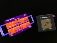
If your Permissions in a room allow you to use the Maker Pen and view gadgets, you can create chips with the “Gadgets” tab of Palette. These chips appear as small black boxes. Most of the chips can be configured with the Configure mode of the Maker Pen. The pins of the chips can be connected and disconnected with the Wire mode of the Maker Pen. In general, input pins to a chip are on the left, and output pins from the chip are on the right. An input can have 0 or 1 connection, an output can have multiple connections. Connections are removed by grabbing the connection from the input pin with the Wire mode and then dropping it.
You can get information about most pins (function of input pins and current values of output pins) by pointing with the ray of the Wire mode at a pin for about 2 seconds. Input pins that are not wired to anything receive a 0 signal unless another constant value is specified with the Configure mode. A true input (any value unequal to 0) to the reset pin (white with "R" printed on it) will reset a chip, that usually means all outputs are forced to be 0.
Multiple chips can be combined in compact Circuit Boards to structure (complex) networks of chips (and hide their complexity).
Examples of circuits with most of these chips are on the page Circuit Diagrams.
For common problems with chips, see the description of pitfalls on the circuits page.
Math Chips
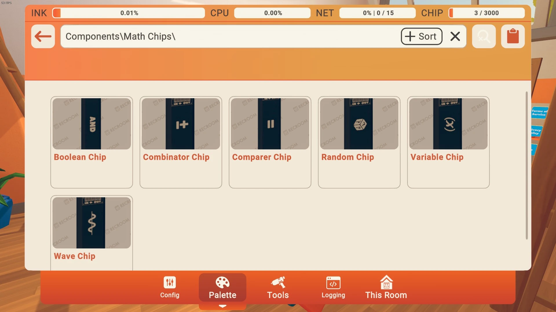
The Math Chips.
This section describes all chips that are available in the "Gadgets" tab of the Palette with the filter "Math Chips". You have to have Permissions to view gadgets and to use the Maker Pen to get access to this tab.
Boolean
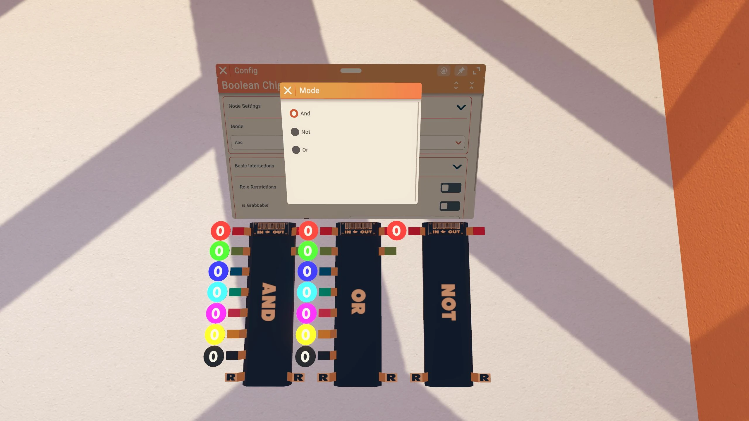
Boolean chips act as logic gates, supporting "And", "Or", "Nand", "Nor", and "Not" operations. You can set the operation with the Configure tool of the Maker Pen.
AND
Inputs:
| Pin | Range | Description |
|---|---|---|
| Red to Black | Boolean | Boolean inputs. |
| Reset | Boolean | Causes both outputs to be false. |
Outputs:
| Pin | Range | Description |
|---|---|---|
| Red | Boolean | True if reset is not set, and all connected inputs are true. False otherwise. |
| Green | Boolean | False if reset is set, or no input is connected, or any connected inputs are false. True otherwise. |
Expert Tip: Converting Values
- You can use a Boolean chip (in either AND or OR mode) to convert a value to 1. This is done by connecting the output to any of the coloured pins on the Boolean chip. This is useful for taking an unknown value (e.g. Player ID) and turning it into a 1.
OR
Inputs:
| Pin | Range | Description |
|---|---|---|
| Red to Black | Boolean | Boolean inputs. |
| Reset | Boolean | Causes both outputs to be false. |
Outputs:
| Pin | Range | Description |
|---|---|---|
| Red | Boolean | True if reset is not set, and any connected input is true. False otherwise. |
| Green | Boolean | False if reset is set, or no input is connected, or all connected inputs are true. True otherwise. |
NOT
Inputs:
| Pin | Range | Description |
|---|---|---|
| Red | Boolean | Boolean input. |
| Reset | Boolean | Causes the output to be false. |
Outputs:
| Pin | Range | Description |
|---|---|---|
| Red | Boolean | True if reset is not set, and the input is connected, and the input is false. False otherwise. |
Combinator


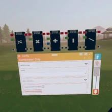
RecRoom Combinator Chip Update
Combinator chips do mathematical operations on inputs. Currently, addition, subtraction, multiplication, division and modulo (remainder after division) operations are supported. You can set the operation with the Configure tool of the Maker Pen.
A common application of the addition operation is to increment a score. Note that to increment a score, you need to connect the output of the chip to one input in order to add the new score to it.
A common application of the modulo operation is to toggle between 0 and 1: by computing an input value modulo 2, the result will toggle between 0 and 1 if the input is incremented in steps of 1.
Comparer


Rec Room Comparer Chip Update
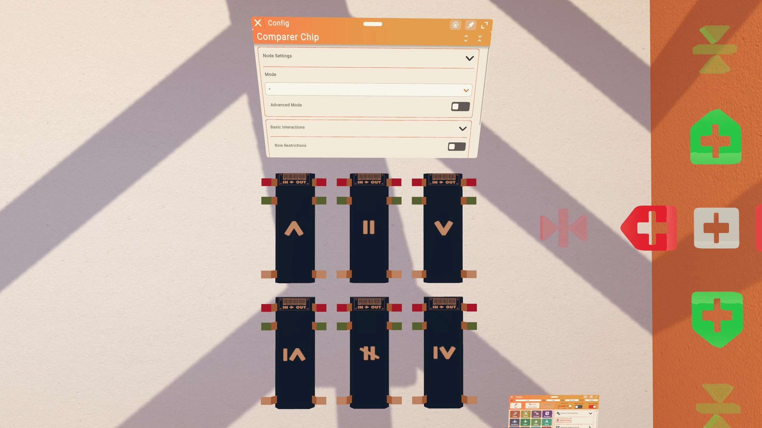
Comparer chips do mathematical comparisons between the red input signal and the green input signal, including equals, not equals, greater than and less than operations. If "Advanced Mode" is not checked in the chip's settings, the red output true if the comparison is true and false otherwise, the green output has the negated value.
In "Advanced Mode" the red output has the value of the cyan input if the comparison is true and 0 otherwise, the green output has the value of the pink input if the comparison is false and 0 otherwise. Often both outputs are directly connected to an addition Combinator in advanced mode.
You can set the comparison and the mode with the Configure tool of the Maker Pen.
Because the Selector chip applies up to 7 comparison functions at once, it is often useful to replace Comparer chips with Selector chips when one of the numbers being compared will remain constant.
Random

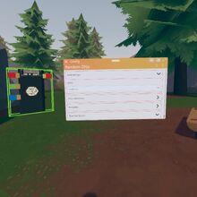
Every tick the red node gets a True signal, the random chip generates an output value with a random number in the range from the green input (inclusive) to the blue input (exclusive). In other words, the value from the green input can appear, the value from the blue input cannot appear. To roll numbers from 1 to 6, input 1 to green and 7 to blue. If the upper and lower bound are equal, that value will be generated, if the upper bound is larger than the lower bound, 0 will be generated.
Inputs:
| Pin | Label | Range | Description |
|---|---|---|---|
| Red | Generate Signal | 0 or ≠0 | The chips generates a new value every tick this input is set. |
| Green | Min | Any | Lower bound of the output (inclusive). |
| Blue | Max | Any | Upper bound of the output (exclusive). |
Outputs:
| Pin | Label | Range | Description |
|---|---|---|---|
| Red | RAND [Green, Blue) | ≥ green and < blue | Generated random value. |
Settings:
| Name | Label | Values | Description |
|---|---|---|---|
| Mode | RAND [Green, Blue) | Continuous, Pulse | Continuous: The output will stay at the last generated value until a new one is generated.
Pulse: The output will only be the generated value in the tick that it is generated, otherwise 0. |
Variable


Rec Room Variable Chip Basics Update
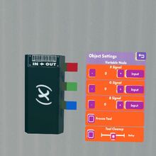
Variable chips hold three integer numbers that are available as output on the pins on the right side. You can set the values with the Configure tool of the Maker Pen.
Wave

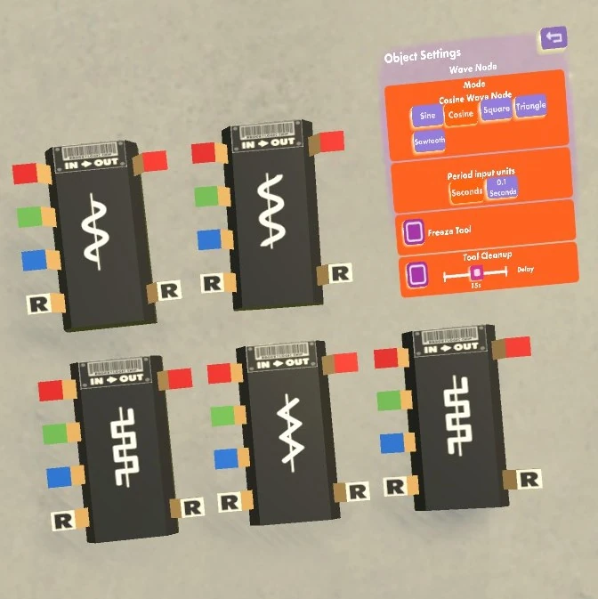
The wave chip outputs a sine, cosine, square, triangle, or sawtooth function of a specified cycle duration and amplitude.
Inputs:
| Pin | Label | Range | Description |
|---|---|---|---|
| Red | ON/OFF | Boolean | True (signal unequal 0) turns the wave function on, false (0) outputs 0 on the red pin. |
| Green | Cycle duration (sec/0.1sec) | Seconds or 0.1 seconds | Determines how long one period of the wave function is. Units depend on settings. |
| Blue | Amplitude | Boolean | The maximum output value. The minimum output value is the negative amplitude for all wave functions. |
| R | Reset | Boolean | True (signal unequal 0) outputs 0 on the red pin. |
Outputs:
| Pin | Label | Range | Description |
|---|---|---|---|
| Red | Signal value | -Blue to +Blue | Outputs a sine, cosine, square, triangle, or sawtooth function of the specified cycle duration and amplitude. |
| R | Reset | Any | Outputs the R input. |
Settings:
| Name | Label | Values | Description |
|---|---|---|---|
| Mode | Mode | Sine, Cosine, Square, Triangle, Sawtooth | Specifies the wave functions. |
| Cycle duration units | Period input units | Seconds, 0.1 Seconds | Specifies the units in which the green input is specified. |
Game Chips

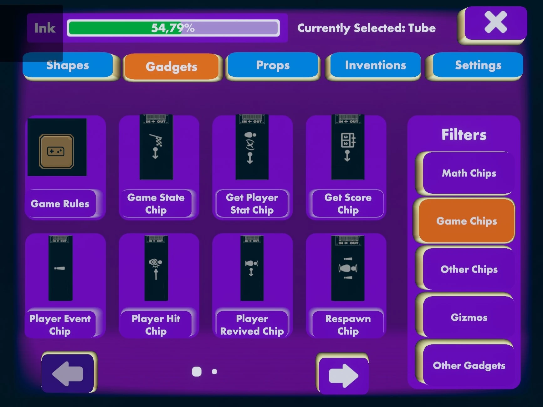
First page of "Game Chips."
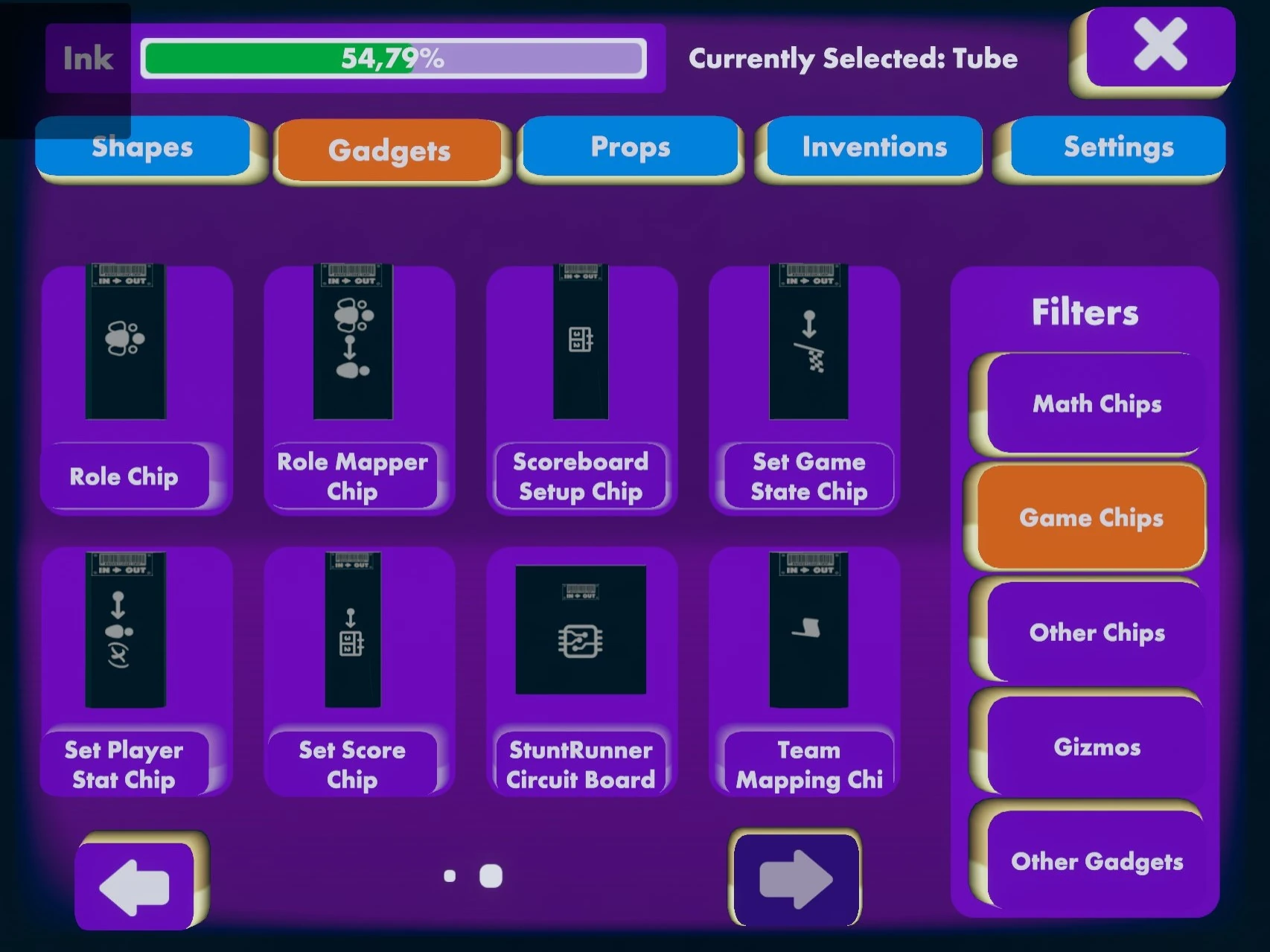
Second page of "Game Chips."
This section describes all chips that are available in the "Gadgets" tab of the Palette with the filter "Game Chips". You have to have Permissions to view gadgets and to use the Maker Pen to get access to this tab.
Game Rules

Each Game Rules Chip specifies a game mode that may be selected by players on a scoreboard. The chip corresponding to the selected game mode outputs a 1 on its output pin. The chip is configured with the Configure mode of the Maker Pen; see the page about the Game Rules Chip for the available settings.
Game State
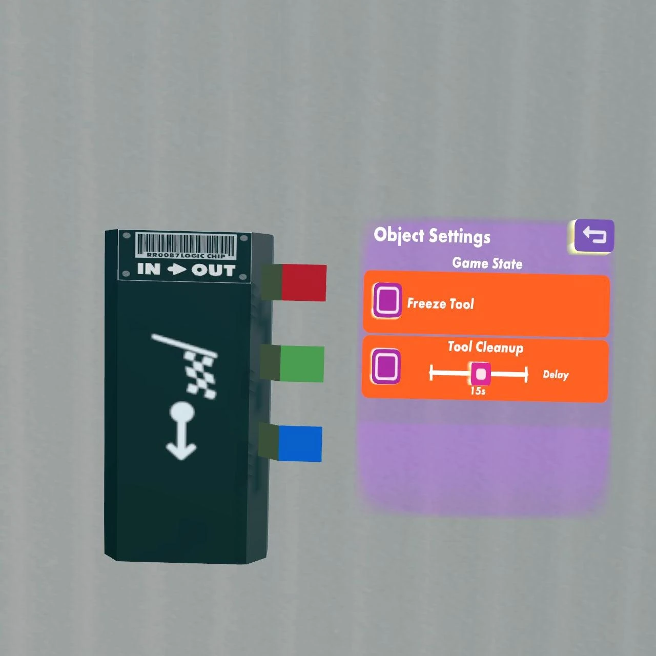
Sends a momentary output of 1 on the appropriate pin when the game state changes:
- Red = Game Start
- Green = Game End
- Blue = Pre-Game Start (5 to 6 seconds before Game Start)
Get Player Stat
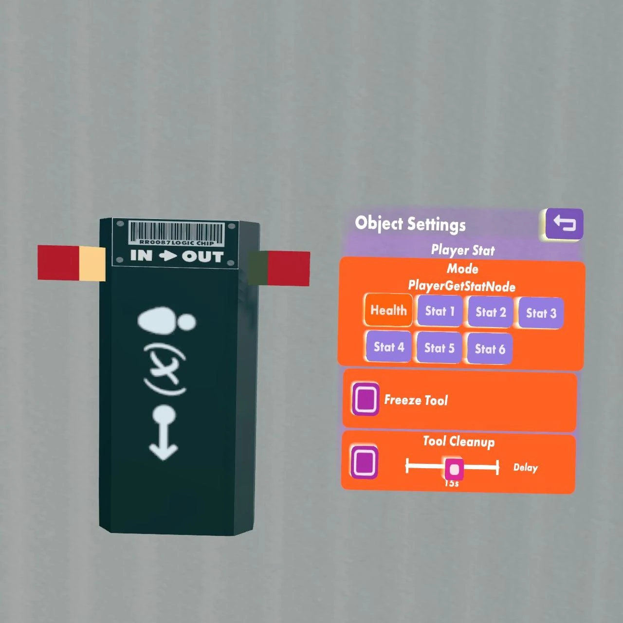
Chip used to retrieve player stats given a player ID. The Red Input Pin takes in a player ID and the Red Output Pin outputs the value stored in whatever stat slot is selected through the chip configure menu.
Get Score

If the red input pin receives a team ID, then the red output pin returns the team's score from the scoreboard. This can be used to make announcements about the score.
Paintball Capture The Flag Circuit Board
[More information needed.]
Paintball Team Battle Circuit Board
[More information needed.]
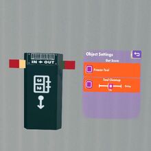
Player Event
A signal is sent from this chip when any of 4 player events occurs:
- When a player joins, their ID is sent from the Red Pin. Note that this event happens some time before the game places the player onto a team, which can override a circuit that assigns teams using this pin. Use a delay chip to avoid this issue.
- When a player leaves, their ID is sent from the Green Pin.
- The count of players in the map is constantly sent from the Blue Pin.
- When a player changes teams, their ID is sent from the Cyan Pin.
Player Hit
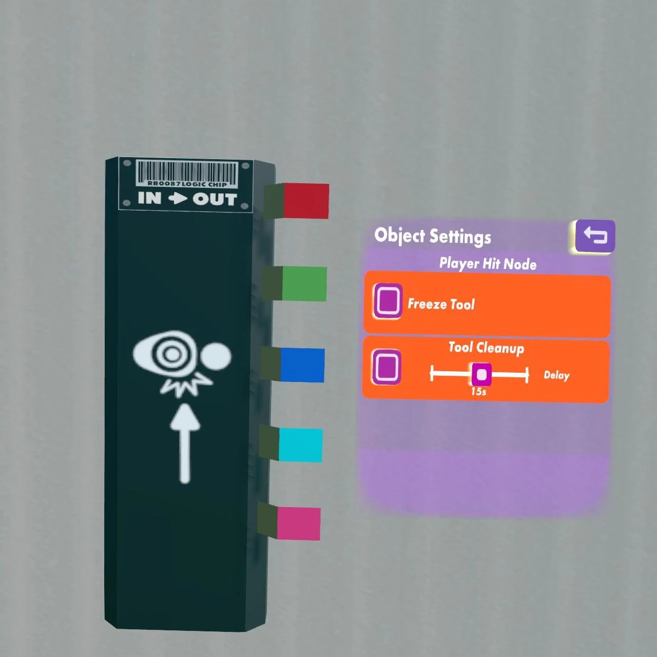

The player hit node can be used to detect who hits someone, and who is hit, and by how much damage. Red outputs the player ID of the attacker, green the player ID of the defender, blue the team ID of the attacker, cyan the team ID of the defender, and pink the damage of the attack.
Other than in other game modes, the damage of weapons is currently constant in sandbox rooms. It does not take into account factors like distance for grenade launchers or how far a bow has been pulled.
Chips are only evaluated about every 10th of a second, but the player hit chip is buffered and therefore does not miss any hits. For example when hitting two players at the same time (with grenades or shotguns). The hit chip outputs both hits in sequence. If multiple hits occur during the tick period, the damage output is combined into a single tick. For example when hitting someone with a shotgun, all particles will be registered during the same tick and therefore output a damage of up to 136 in a single tick instead of 17 ticks of 8 damage. The Laser Burst Gun appears to fire about 15 shots per second and therefore outputs damages of 5 or 10 for body shots. Different than in previous updates, this also means that a weapon cannot be identified by its damage anymore.
Weapon damages: Chart
Player Revived
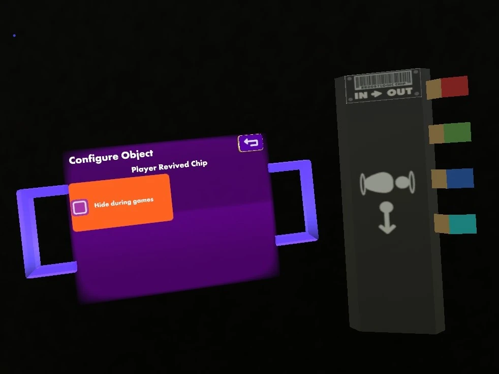
This chip sends a signal whenever a player is revived. The four output pins are labeled "Revived Player", "Reviving Player", "Team", "Revived Player Health". (need explanation of pins 'team' & 'revived player health')
Respawn
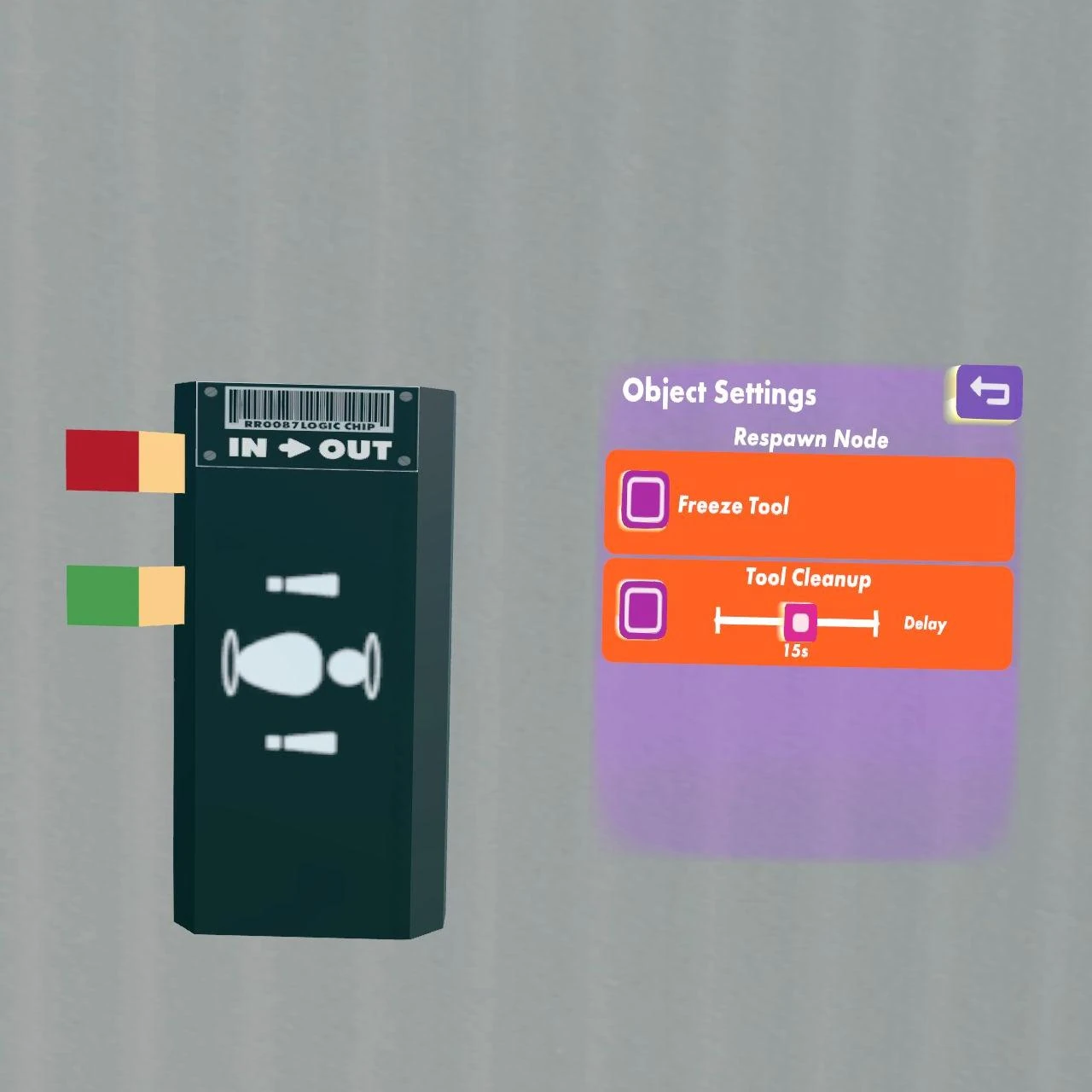
The red input accepts a player ID and respawns that player on a valid respawn point. The green input respawns the entire team, where a signal of 1 is the blue team, 2 the red team, etc. -1 (or any negative value) respawns players of all teams.
Role

How to set up Roles in your rooms! (games - flying - wall running - voice volume)
YouTube tutorial by Rec Room Inc.
The Role chip allows you to specify a (game) Role. Configuring the chip allows you to edit the role in two tabs:
- Shared tab:
- Can Move (No/Yes)
- Can Fly (No/Yes)
- Can Switch Teams (No/Yes)
- Pickup Restrictions (None/Restrict All/Allow [Object] Tags/Block [Object] Tags)
- Hip Equip Slots Enabled (All Disabled/One Enabled/Both Enabled)
- Hip Equipment Restrictions (None/Restrict All/Allow [Object] Tags/Block [Object] Tags)
- Shoulder Equipment Restrictions (None/Restrict All/Allow [Object] Tags/Block [Object] Tags)
- Voice Rolloff Distance (0m/1m/5m/10m/25m/50m/100m/500m)
- Hide this Player's Name (No/Yes).
- Locomotion tab:
- Teleport Delay (0.1s to 30s)
- Teleport Distance (0.5m to 30m)
- Walk Speed (0.25m/s to 8m/s)
- Jump Height (0.1m to 40m)
- Can Sprint (No/Yes)
- Auto Sprint (Off/On)
- Slide Down Slopes (No/Yes)
- Sprint Speed Multiplier (1x to 2.5x)
- Can Wall Run (No/Yes)
- Can Get Pushed (No/Yes)
- Can Ram (No/Yes)
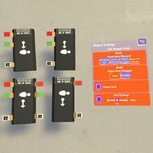
Role Mapper
The role mapper chip can assign a (game) Role to a player or team; remove the role; query whether a player has a role, and query whose player's roles have changed. If a chip should use a non-standard Role, the role should be defined before you configure the chip.

Inputs:
| Pin | Label | Range | Description |
|---|---|---|---|
| Red | Player | A valid player ID | The player ID of the player who should have a role added, removed, or queried. |
| Green | Team | A valid team ID | The team ID of the team that should have a role added or removed. |
Outputs:
| Pin | Label | Range | Description |
|---|---|---|---|
| Red | Player | A valid player ID | Outputs the player ID of the relevant player only if that player does have the defined role. This is useful for enabling circuit functions only for certain players. |
| Green | Has Role | Boolean | True (1) if the player has a role; false (0) otherwise. |
Settings:
| Name | Label | Values | Description |
|---|---|---|---|
| Mode | Mode | Add Player Role, Remove Player Role, Player has Role, Player Role Changed |
|
| Player Role | Mode | Any non-standard Game Role | Any of the non-standard Roles. |
Scoreboard Setup
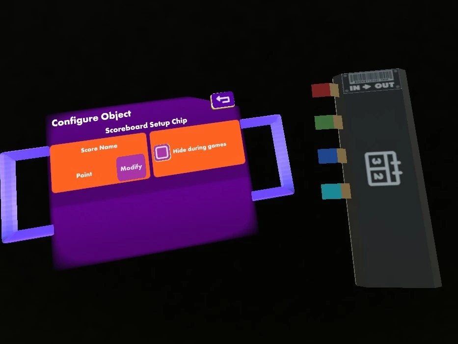

This chip controls the Scoreboard Projector. It has four input pins: "On/Off" (unqueal to 0 (True) displays the score and time on the scoreboard), "Time (s)" (the remaining time displayed on the scoreboard; also controls the game end countdown), "Duration (s)" (the game duration displayed on the scoreboard during pre-game), "Max Score" (maximum possible score - it's unclear whether this has an effect currently).
Set Game State
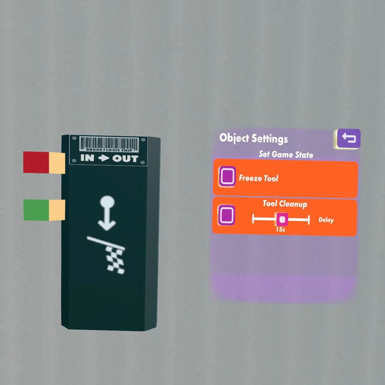
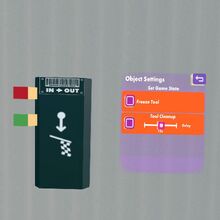
A signal unequal to 0 (True) on the red pin starts the game (or more precisely: it starts the pre-game sequence and after 5 to 6 seconds, it starts the game). A signal unequal to 0 (True) on the green pin stops the game.The game length is set in the Watch Menu: This Room, Game Setup.
Set Player Stat
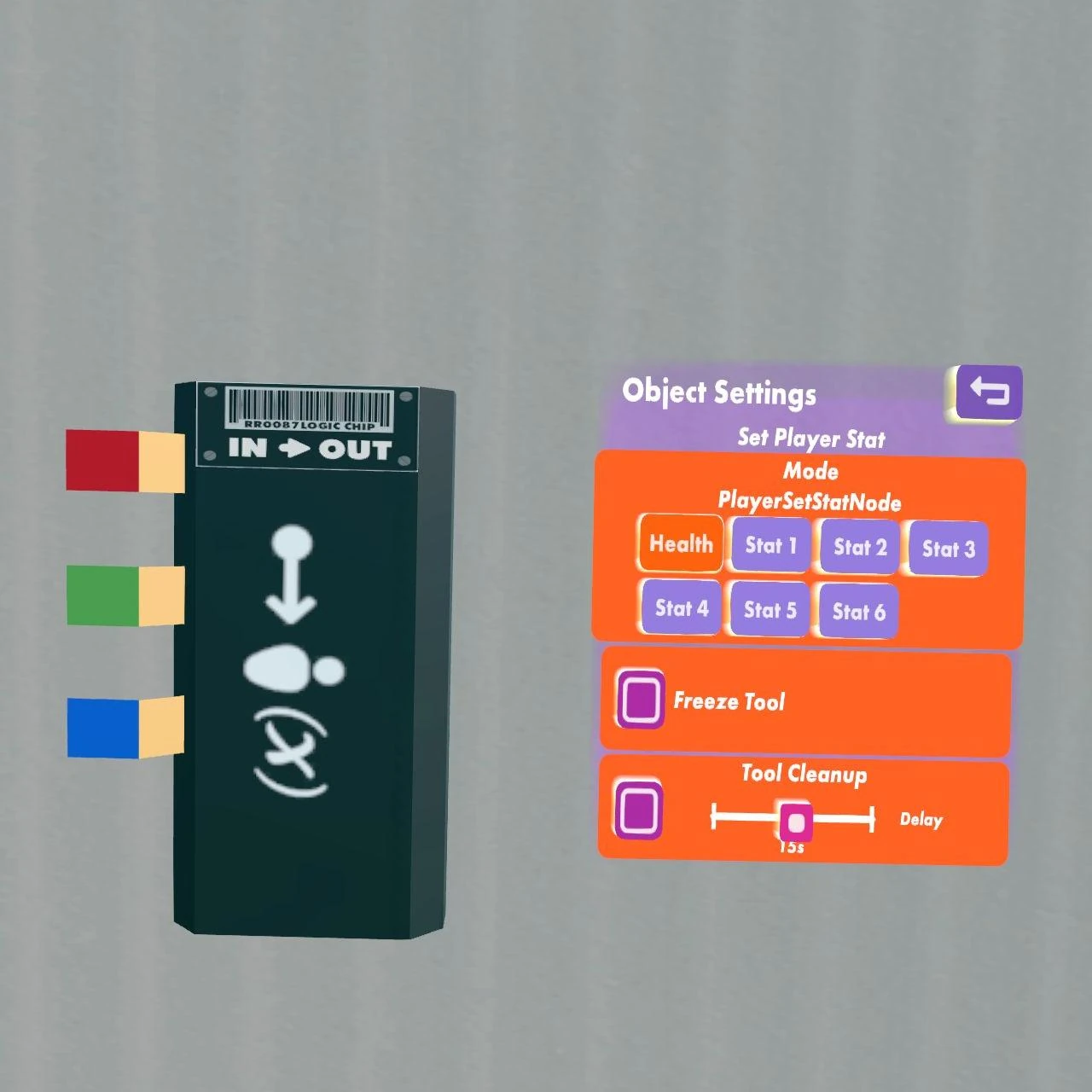

This chip is used to set the value of a stat for one player, or for all players. If the green pin is set to a value greater than 0 (True), then the value supplied in the blue pin is assigned to the stat selected in the settings of the player with the player ID that is specified by the signal in the red pin. Sending a -1 to the red pin sets the stat of all players.
Stats can only be set when a game is in progress. "Stat1" shows up on the score board.
Setting the Health stat to 0 (or less) puts the player in a dead state similar to paintball where they immediately drop their weapons, see everything in black and white, and lose the ability to interact with objects and to teleport.
(need info here on the new shield stat)
All player stats are set to their defaults when a player changes teams. The defaults are 0 for all stats except for Health which has a default of 1.
Set Score
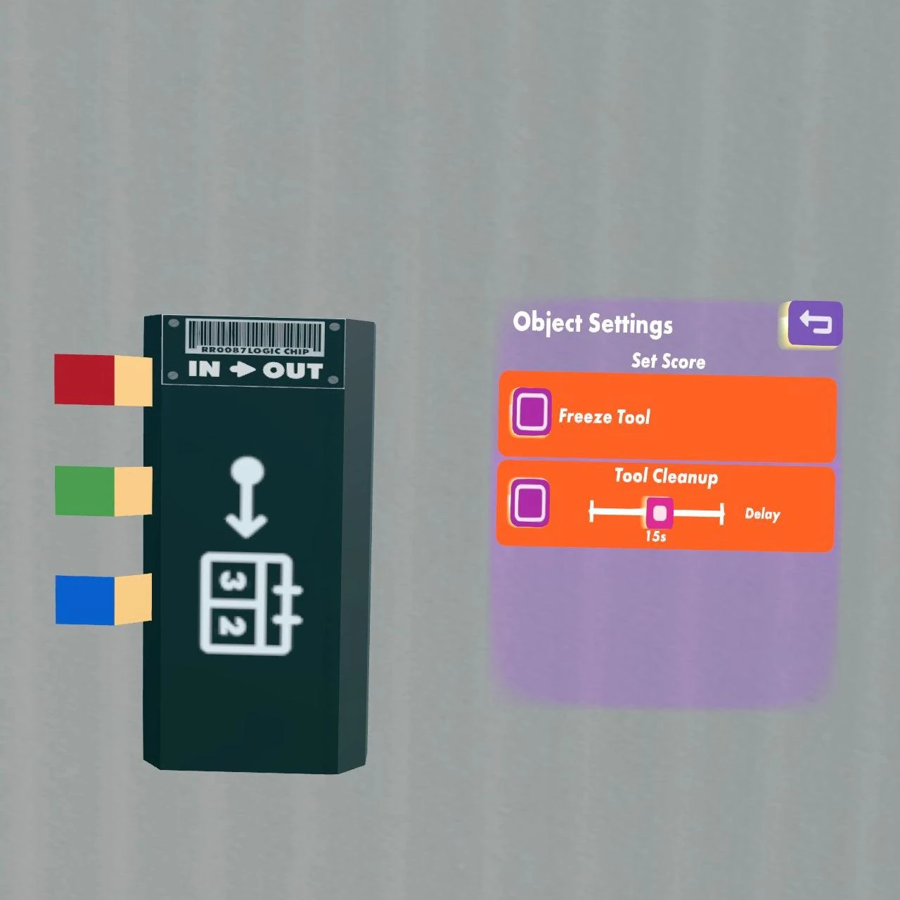
If a game is in progress and the green pin receives True (a signal unequal to 0), then the number on the blue pin is set as score of the team with the team ID on the red pin.
StuntRunner Circuit Board
A circuit board that provides some of the functionality of Stunt Runner. [More information needed.]
Team Mapping

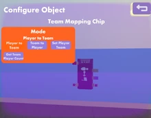
Use the Configure tool of the Maker Pen to change the modes of this chip. (need info here on whether output is steady or pulse)
Player to Team
Input a Player ID to receive outputs of Team # (green pin) and Team Index (blue pin).
Team to Player
Input a Team # together with a Team Index to receive output of a Player ID if a player is occupying that Index. If no player has that Index, the chip will output 0.
Set Player Team
Input a Player ID together with a Team # to move the player to that team.
Get Player Team Count
Input a Team # to receive an output of the number of players currently on that team.
Other Chips

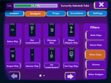
First page of "Other Chips."

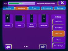
Second page of "Other Chips."
This section describes all chips that are available in the "Gadgets" tab of the Palette with the filter "Other Chips". You have to have Permissions to view gadgets and to use the Maker Pen to get access to this tab.
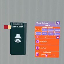
Background Objects

Moods Chips
[More information needed.]
Delay
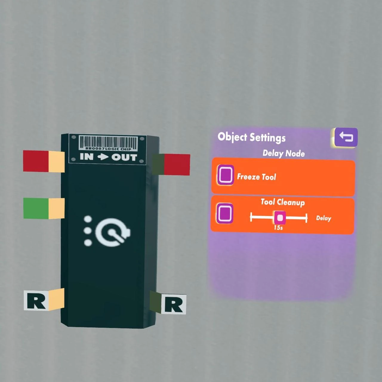
Delay chips take a signal passed on the red pin, wait the amount of time provided by the green pin (in circuit ticks, i.e. 10th of seconds), and then output the signal from the red input pin momentarily on the red output pin before outputting 0 again, even if the input stays on a different value. It will emit a pulse again, if the input value changes to a different non-zero value. The minimum delay time (green input) is 1, even if you don't connect anything to the delay input.
If new signals come in before the last one is put out, the delay chip buffers the latest 20 signals (value + delay) and outputs them in the correct order.
Fog
Moods Chips
[More information needed.]
Get Leaderboard

Get Leaderboard Chip!
This chip retrieves persistent per-player stats that have been set with the Set Leaderboard chip and are displayed by the Leaderboard Projector.
[More information needed.]
Message
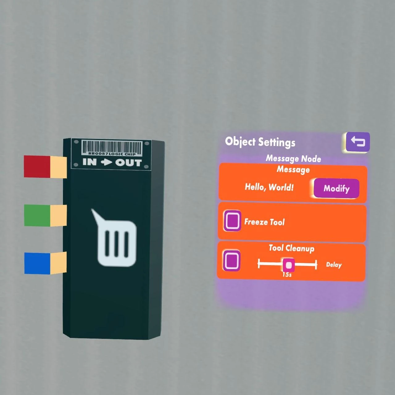
Message chips display a message to all players in a room when the red input pin is set to true. The message is sent to only one player when the green pin is set to a player ID. The message is sent to all players on one team, if the blue pin is set to a team ID. The message can be edited with the Configure tool of the Maker Pen.
If a Message includes {R}, then the nonzero value sent to the Red input pin will be displayed in its place. This can only be done for messages sent to all players. For example, the message "Player {R} has died!" will display "Player 2 has died!" to all players when the Red pin receives an input of 2.
Object Mapper
Input a valid object ID to receive output of the player ID of the player who last held the object and the player currently holding the object, if any. In order to continuously monitor an object, the chip must continuously receive that object's ID.
| Pin | Label | Range | Description |
|---|---|---|---|
| Red input | Object ID | valid object ID | Object ID (e.g., from Trigger Zone) |
| Red output | Last Held Player | 0 or a player ID | Player ID of the player who last held the object if the object is not currently held, or the player who is currently holding the object if it is held. See update 4-23-2019 below |
| Green output | Currently Holding Player | 0 or Player ID | Outputs the Player ID of the player currently holding the object if it is held. Outputs 0
if the object is not held. |
IMPORTANT: The output pins do not update themselves after signal input stops! This means that the output pins will continue to output the same Player ID regardless of whether a new player has picked up that object. Send any negative number to the input pin to reset both outputs to 0, or send the same object ID continuously to receive continuous updates for the object.
UPDATE April 23 2019: "Object-Player Mapping chip's 'Last Held Player' output has changed. Instead of changing current player output when an object is picked up, it now outputs the previous holder's ID until the object changes hands."
Output

Output chips display the numeric value input on the red pin on the left.
Selector Chip
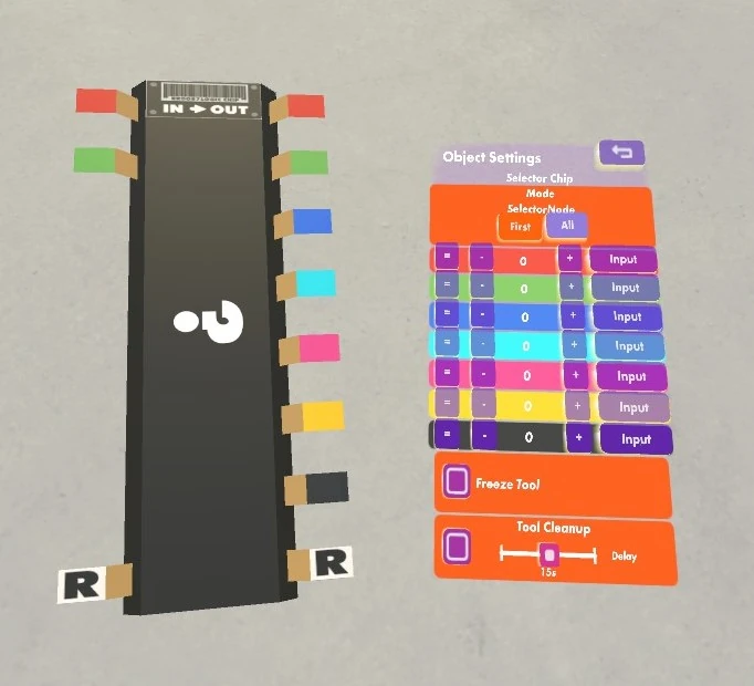

The selector chip has two modes that can be set with the Configure tool of the Maker Pen: "First" and "All". The selector chip compares the red input signal with the numbers of output pins that are specified in the settings of the chip.
If the mode is set to "First", the chip sends the green input signal to the first output pin that has the same number as the red input signal. "First" searches the list of conditions starting at the top and working its way down. All other output pins are set to 0.
If the mode is set to "All", the chip sends the green input signal to all output pins whose conditions are satisfied by the red input.
This configuration is important when using "greater than" or "less than" conditions. For example, an input of 7 will satisfy all the conditions of "greater than zero," "greater than 6," "equal to 7," etc., and thus the "All" configuration would send the signal to all of those pins, while the "First" configuration would only send the signal to the satisfied condition highest on the list. Therefore, the order in which conditions are listed is important when using the "First" configuration.
A Selector chip is sometimes useful for replacing one or more Comparer chips when the values being compared will remain constant.
Set Leaderboard

Leaderboard Chip and Projector
Sets one of the persistent stats for a player, which are kept even after a player has left a room. These stats can be retrieved with the Get Leaderboard chip and displayed with the Leaderboard Projector. Note that the leaderboard data takes a while to update. To set a highscore, you would usually compare the player's current score with the score from the Get Leaderboard chip and only set a new leaderboard stat if the current score is higher.
[More information needed.]
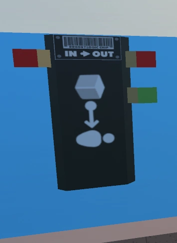
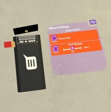
Set Tags
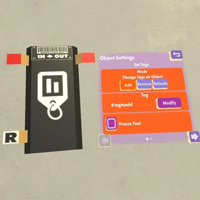
The set tags chip can add or remove tags to or from an object. You can also set object tags manually with the Configure mode of the Maker Pen. Object tags can be used by LookAt Gizmos, Trigger Volumes, Object Respawners, Respawn Points, and Pickup/Equipment Restrictions of Roles.
Inputs:
| Pin | Label | Range | Description |
|---|---|---|---|
| Red | Object ID | A valid object ID | The object ID of the object which should have a tag added, removed, or set to defaults. |
Outputs:
| Pin | Label | Range | Description |
|---|---|---|---|
| Red | Object ID | A valid object ID | If successful, the object ID of the relevant object. Otherwise 0. |
Settings:
| Name | Label | Values | Description |
|---|---|---|---|
| Mode | Mode - Change Tags on Object | Add, Remove, Defaults | Add: adds the specified tag to the object. Remove: removes the specified tag from the object. Defaults: restores the default tags. |
| Tag | Tag | Any valid tag text | Specifies the tag that should be added or removed. |
SFX

A sound effect is played whenever the input value changes to a new non-zero value. Thus, a sound will play when a True signal is sent, but it will also play, for example, when a score increases or decreases (unless the new score is 0).
You can change the sound effect played by using edit mode of the maker pen. The sounds effects available are:
| Blue Scores | Red Scores | Blue Wins | Red Wins |
| Tie Game | Goal | Hit | Buzzer |
| Game Over Bell | Revive | Ding | Score |
| Whistle | Whistle down | Whistle up | Ding ding! |
| Sparkle | Subsonic boom | Golf clap | Snare drum |
| Horn | Beep | Explosion | Boot up |
| Thud | Splash | Rez in |
SkyDome
Moods Chips
[More information needed.]
State

State chips are part of State Machines. The three output pins are labeled "OnEnter", "InState", "OnExit". Note that you cannot connect these pins to anything unless the state chips itself is wired directly or indirectly to a State Machine chip. The configuration of the state chip specifies a minimum time for how long the state is active, 3 values (which are sent by the State Machine chip if the state is active), and a name of the state.
State Machine
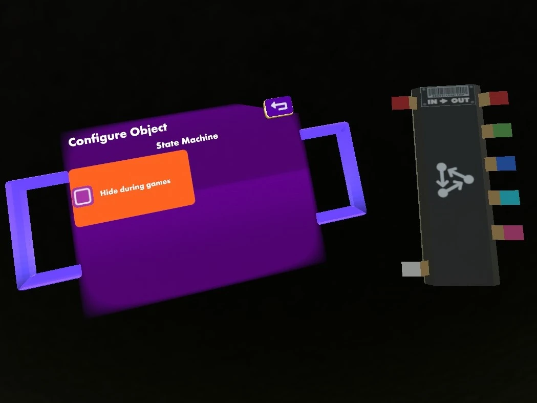
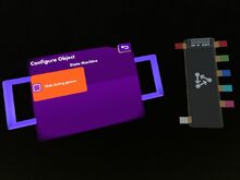
One State Machine chip is (together with State chips) part of each State Machine. It has a reset input pin that resets the current state to the state that is directly wired to the state machine chip. The other input pin disables the state machine if it receives a 0 signal. The 5 output pins are labeled "Val1", "Val2", "Val3", "TimeInState" (in ms), "OnChange". The 3 values are determined by the configuration of the currently active State chip.
Timer
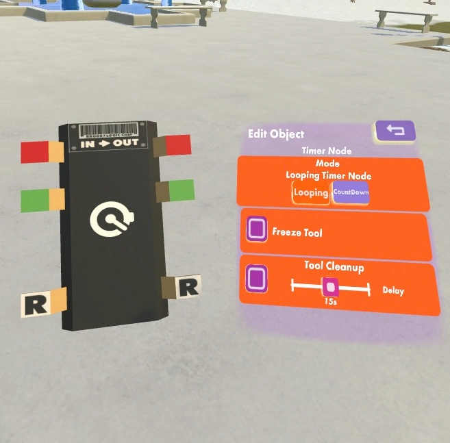

Timer chips can be used in countdown or looping countdown mode. The red input pin is an on/off switch; the timer must be held in an “on” state to operate. Thus, a button press, which only sends a momentary signal, cannot run a timer on its own.
The Timer has a known bug where the countdown will reset when the Authority Player leaves and the game migrates to a new player. One workaround for this is to replace a Timer with some equivalent circuit, like an Event Sequencer.
Inputs:
| Pin | Label | Range | Description |
|---|---|---|---|
| Red | On/Off | Boolean | Turns the timer on or off. The timer is running while the input is true, and paused otherwise. |
| Green | Duration | In 0.1 seconds | Determines how long the timer will run, e.g. 50 for 5 seconds. Changing the input will result in a reset. |
| Reset | Reset | Boolean | Resets the timer. It will take the full duration specified by the green input to run. |
Outputs:
| Pin | Label | Range | Description |
|---|---|---|---|
| Red | Signal | Boolean | Outputs true for a single tick when the timer expires. |
| Green | Remaining | Seconds | Outputs the remaining seconds until the timer expires.
|
Settings:
| Name | Label | Values | Description |
|---|---|---|---|
| Mode | Looping Timer Node | Looping, Countdown | Looping: The timer will reset automatically when the timer expires. This is the same as connecting the red output to the reset input.
Countdown: The timer has to be reset manually (reset input). |